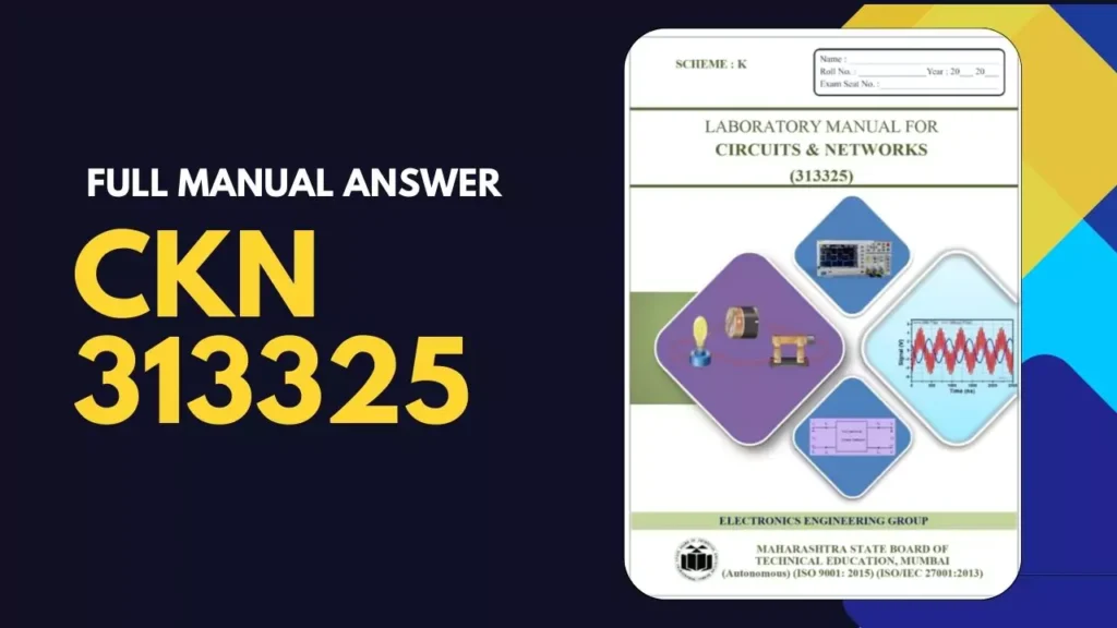
Welcome to PracticalKida, this blog post is special for Electronics & Telecommunications third-semester students. All practicals answer for 313325 CKN Circuits & Networks Manual are given below.

Circuits & Networks 313325 CKN Manual Answer
| Sr.No | Practical No | Answer |
| 1 | Measure the voltage across resistive circuit and verify it, using Kirchhoff‘s Voltage law (KVL). | Click Here |
| 3 | Measure current through and voltage across given branch of electric network and verify it by mesh analysis. | Click Here |
| 4 | Measure voltage at particular node and current through branch of network and verify it by nodal analysis. | Click Here |
| 6 | Observe transient response of RC series circuit with DC excitation. | Click Here (Added Soon) |
| 7 | Measure current through given branch of network and voltage across given element of the circuit and verify it applying Superposition theorem. | Click Here (Added Soon) |
| 9 | Measure open circuit voltage and thevenin’s resistance of the given circuit and verify it using Thevenin‘s theorem. | Click Here (Added Soon) |
| 10 | Vary load resistance to transfer Maximum power in the given circuit using maximum power transfer theorem. | Click Here (Added Soon) |
| 12 | Measure input and output voltages and currents of the given two port network and calculate open circuit (Z) parameters for the given circuit. | Click Here (Added Soon) |
| 16 | Develop RC high pass filter on breadboard and plot its frequency response | Click Here (Added Soon) |
| 18 | Test the performance of Symmetrical T attenuator. | Click Here (Added Soon) |
| 20 | Measure voltage and current in the given R-L series circuit and calculate active, reactive and apparent power consumed in the circuit. | Click Here (Added Soon) |
| 22 | Measure voltage and current in the given R-L-C series circuit and calculate active, reactive and apparent power consumed in the circuit. | Click Here (Added Soon) |
| 23 | Measure voltage and current in the given R-C parallel circuit and calculate power factor, active, reactive and apparent power consumed in the circuit. | Click Here (Added Soon) |
| 25 | Measure voltage and current in the given R-L-C parallel circuit consists of series connection of resistor and inductor in parallel with capacitor and calculate power factor, active, reactive and apparent power consumed in the circuit. | Click Here (Added Soon) |
| 28 | Measure voltage and current in the given RLC series circuit and calculate resonance frequency and impedance at resonance using variable supply frequency. | Click Here (Added Soon) |
| 30 | Measure current of given RLC parallel circuit and calculate resonance frequency and impedance at resonance by varying supply frequency. | Click Here (Added Soon) |
Conclusion
In this blog post, we provided solutions for all practicals of Circuits & Networks 313325 CKN Manual. We hope this information helps students.

